Redline Markup on Electrical Plans
By knowing how to do Levven planning and markup, you can:
- Minimize material costs
- Give field crews plans they can follow to wire and trim homes
- Know what Levven products are needed to complete the installation
- Make potential future service easier by marking Levven controller locations
Wire Markup
Two-conductor wire (2C) is represented by a 1-point dashed line.
Three-conductor wire (3C) is represented by a heavier 3-point dashed line.
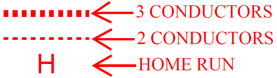
The home run is 2C wire directly from the electrical panel to a box with fixture or controller. Mark it with an "H" on the plan.
Blue Pairing Plate
Levven markup denotes the location of the Blue Pairing Plate with a blue circle.
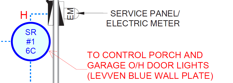
The Blue Pairing Plate contains one GPC10 power controller and is installed in a single-gang box. It's typically located near the electrical panel to control the light in that room.
Add a home run from the electrical panel to the Blue Pairing Plate, and then wire to the switched load and continue with power to the next controller.
See Installing the Blue Pairing Plate for more details.
Box Fill
Verify box fill requirements with your local electrical code.
Each single-output Levven controller counts as two conductors for box fill. Typically, each junction box may contain a maximum of 12 conductors.
Use a junction box with an extension ring if you need to install two controllers in the same junction box.
Constant Power
Each controller needs constant power for proper operation.
When there is a second controller after the first controller's load, and the first controller is switching multiple fixtures, use 3C wire.
Wire Between Junction Boxes
Add 2C and 3C wire to provide constant power to each controller, and connect controllers with their switched loads.
Aim for short wire runs and avoid areas where there may be a significant amount of mechanical equipment
Smoke Detectors
Smoke detector junction boxes may be used for controllers switching other loads (such as a ceiling fan).
Use 2C wire to the first smoke detector and use 3C wire between smoke detectors.
- Box fill is 9C + one single-output controller. Beyond this, use an extension ring.
Add Labels for Junction Boxes
Adding labels for each junction box which contains a controller tells the installation crew:
- Which kind of junction box to use
- Which controller is installed in the junction box
- How many conductors enter and exit the junction box
Box Types
Levven | Description | Capacity | Equivalent Part Numbers |
DP | Deep plastic box, 25 cubic inch | One controller only | US: Carlon BH25HP Canada: Nutec WOCT |
DPWE | Deep plastic box, 25 cubic inch, with 2-inch extension ring | One or two controllers | US: Carlon BH25HP and 2-inch box extender Canada: Nutec WOCT and 2-inch box extender |
4MBR | 4” x 4” box with device mud ring | One or two controllers | US: Carlon B432ARR-UPC and 1-Gang Single-Device Flat Square Cover Canada: Nutec WRD and 1-Gang Single-Device Flat Square Cover |
SRP | Single-gang receptacle box | One controller only | US: Carlon B122A Canada: Nutec WSW |